The Rat Tail
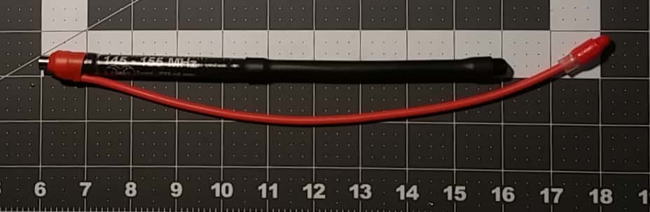
A simple but significant, and inexpensive improvement that can be made to any HT antenna is the creation of counterpoise assembled from cheap components that create a virtual ground plane system commonly referred to as a "Rat Tail". The effectiveness of a counterpoise element is not a myth, it is pretty simple science and therefore not about to make anyone millions. A counterpoise for a VHF handheld radio's antenna typically consists of an insulated wire that is integrated to the radios negative framework and used as a substitute for an earth (ground) reference plane for a radio's active vertical element (the rubber duck antenna). It is used with radio transmitters or receivers when an inferior earth ground presents high soil resistance, or acts as a capacitor. This is a typical condition experienced by Search and Rescue teams on porous soil, snow, using a handheld from the cab of a vehicle, etc. A counterpoise adapter for a VHF rubber duck antenna may also be referred to as a 'Tiger Tail'. A counterpoise, when introduced to a 1/4 wave rubber duck antenna, will increase gain and effectively transform the antenna system into a 1/2 wave dipole. Technically, counterpoise is is not a true ground plane, it would more accurately be referred to as a 'virtual ground plane'. You may have seen radial elements at the bottom of a base station antenna on a roof somewhere, and these are there to give counterpoise. So in the case of a rubber duck, counterpoise gives a virtual ground plane reference to trampoline the signal using the same dynamics analogous to what radials do for base station antennas. This popular 'Rat Tail' phrase to denote a generic passive counterpoise element often can cause some misunderstanding as there is also a commercial product called a 'Rat Tail' that is an antenna signal booster. But in radio enthusiast Forums especially, it also appears to be commonly misunderstood to be a counterpoise element who's function is to provide a virtual ground plane. In fact it is a passive device that uses capacitive coupling to transfer energy from the radiating element of the radio to a wire that dangles from the interface. It also incorporates an LED, the intent of which is to act as a visual energy strength indicator to assist the user to find the optimal spot to stick the device onto the radio. (While this is also probably important to eliminate electrical noise resulting from parasitic capacitive coupling, we found we could not differentiate differences in the LED intensity that helped us with finding an optimal placement location). Further with regard to boosting a signal, keep in mind that doubling the output power will not double the range, the theoretical improvement is about 35-40%. The best way to improve signal performance of a radio is to use a high gain antenna that is properly tuned to match the frequencies it will be used to transmit on, and thus minimize the degrading of both the radio's components and the signal propagation caused by standing waves. You will often hear someone mention that such and such a model or brand of radio performs much better than some other model or brand. What they usually do not realize is when they are quoting the radio that had the best performance, they are probably referring to the radio that had the best antenna that matched the frequency they were on, and offered the most 'Gain'. With HT's, generally the make and model of the radio is a minor consideration whereas when it comes to how far you can transmit, and the proper tuning and optimization of the antenna system is *EVERYTHING*.